That circuit is a real mind bender! Outwardly, though, it seems like it will be a blast to use - lotsa different sound options, and not riddled with controls.
The slide switch has two independent layers/wafers/discs - each with identical pin and switching configs. On that schematic above, I had just added your pin labeling from those switch diagrams that you posted (the numbers labeled in red), and I had arbitrarily labeled the two discs as "disc 1" and "disc 2". It doesn't really matter which disc ends up being disc1 or 2 - just as long as you remain consistent once you choose.
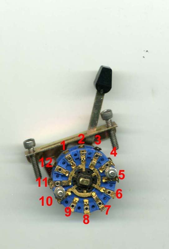
Here's a view of the actual switch with your pin labeling superimposed:
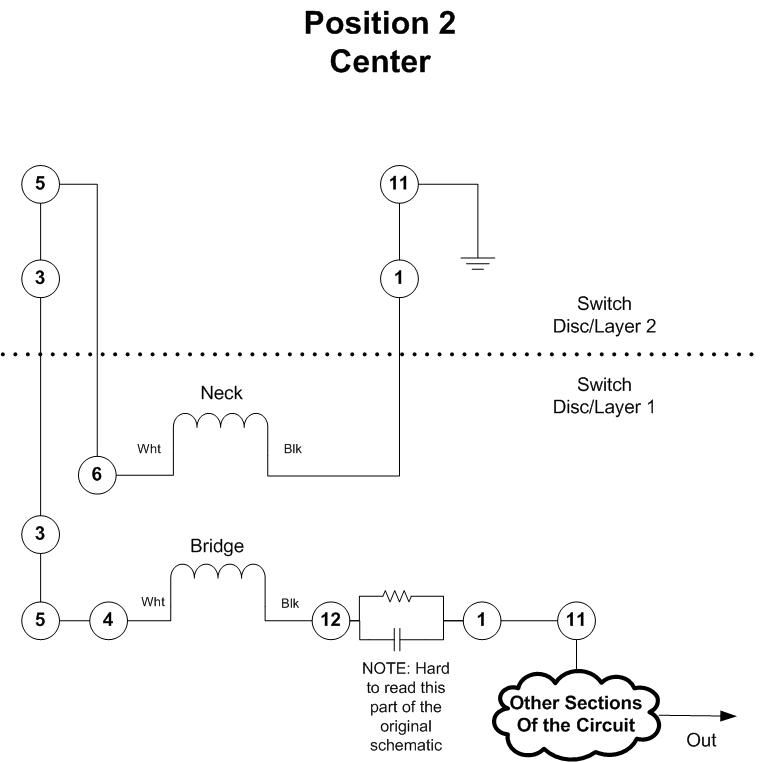
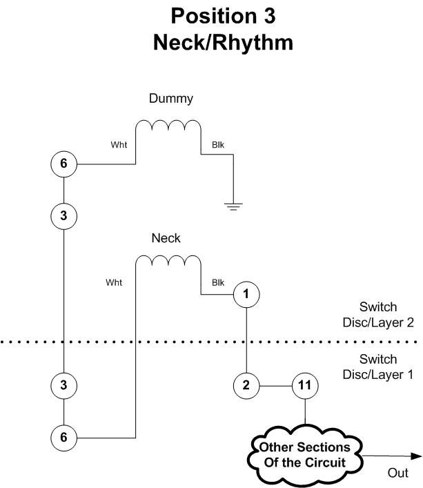
It's really hard to follow the flow of things looking at that schematic, so I drew up some logical diagrams that will hopefully help demystify the pickup switching a bit. In these diagrams, the two discs are represented above and below the dotted lines, and the relevant pins on each disc are labeled within the circles. You can see how the wiring, in some places, hops all over the place just to connect two pickups together. It's like a sadistic game of connect the dots!

Keep in mind that there are sometimes additional, superfluous connections in a given switch position that are not represented in these diagrams for the sake of clarity. Those likely come into play in other switch positions.
So - that said, this is how the slide switch would work to wire things up according to the schematic above:
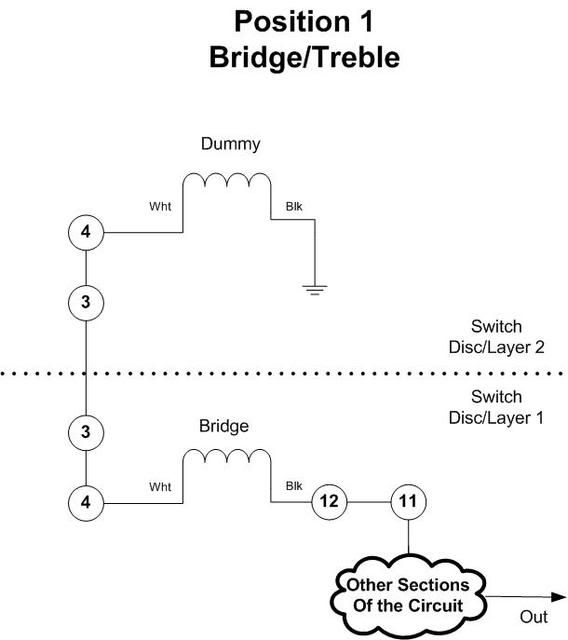
(NOTE: a line from the bridge pickup to pin "4" should be there - it disappears when I post the drawing and it gets resized)
Does that make any better sense of the pickup switching?? It's hard to put into words what is going on there! I'll do my best to help if you run into any snags when wiring this up. I'm not really sure about the color coding on the wiring for those pickups - I would probably just let the Ohm-meter do the talking there - see which combination(s) of wires gives you the impedance you are expecting, and go with that.


